This is a mirror of a campaign update originally posted on CrowdSupply.
Hello again!
Thanks so much to everyone for continuing to support our campaign! We're so excited we'll be able to get our little music player into so many people's hands and pockets!
So far we've talked a lot about Tangara being "easy to hack on" and we've shown you a few small examples. But what about larger changes to your device? In this update, I'll be walking through the process of creating a totally custom faceplate. Specifically, it'll be a faceplate that uses a physical rotary encoder, rather than a capacitive touchwheel.
This is a great little project that's very easy to design and cheap to build. The most difficult part will be soldering the small pitch 15-pin FFC connector.
If you're interested in diving deeper, the sources for this design are all available on Sourcehut.
Constraints
We want our custom faceplate to be compatible with an unmodified Tangara mainboard, so we don't have to build a totally new device. Mostly, that means we need to reuse the same general faceplate form factor (the size, mounting hole locations), as well as the same FFC connector and pinout.
The FFC connector has 15 pins, including:
- 3v3 power
- Ground
- An I²C bus (SCL and SDA)
- A half-duplex SPI bus (SCLK, PICO, CS)
- Three extra GPIO pins, connected directly to the ESP32
The display -- which we'll leave unchanged -- uses the SPI bus and two GPIOs. This leaves us with one spare GPIO, which we can use either as a CS line for a second SPI device, or as an interrupt line for an I²C device.
This may not sound like a huge array of possibilities, but remember that it's very easy to "add" extra GPIO lines by using a cheap microcontroller configured as an I²C device.
Selecting Parts
For our rotary encoder, we'll be using a low-profile "scroll wheel" from Adafruit. It clicks in a way that feels nice, the extra buttons it includes are handy to have, and it's small enough to not add too much bulk to the device.
To act as an interface between the encoder and the ESP32, we'll be using a small microcontroller. I happened to have some Microchip ATTINY816s left over from a previous project and they're very easy to implement (although flashing is a slight pain), so I'll use one of those.
The rest of the parts used are the same as Tangara's production faceplate; some passives, a MOSFET, an FFC connector (all available on Mouser), and a display panel (Adafruit actually stocks these too!).
Making a Schematic
The easiest way to start on the electrical design for our faceplate is to take the existing faceplate KiCad files, make a copy, then delete the parts we don't need. In this case, I deleted the touchwheel controller, the test points, and the haptic motor driver (who needs haptics when you have a real physical dial!).
Adafruit provide a schematic symbol for their touchwheel and the ATTINY816 has a symbol built into KiCad, so adding them into the schematic and wiring them up is a breeze:
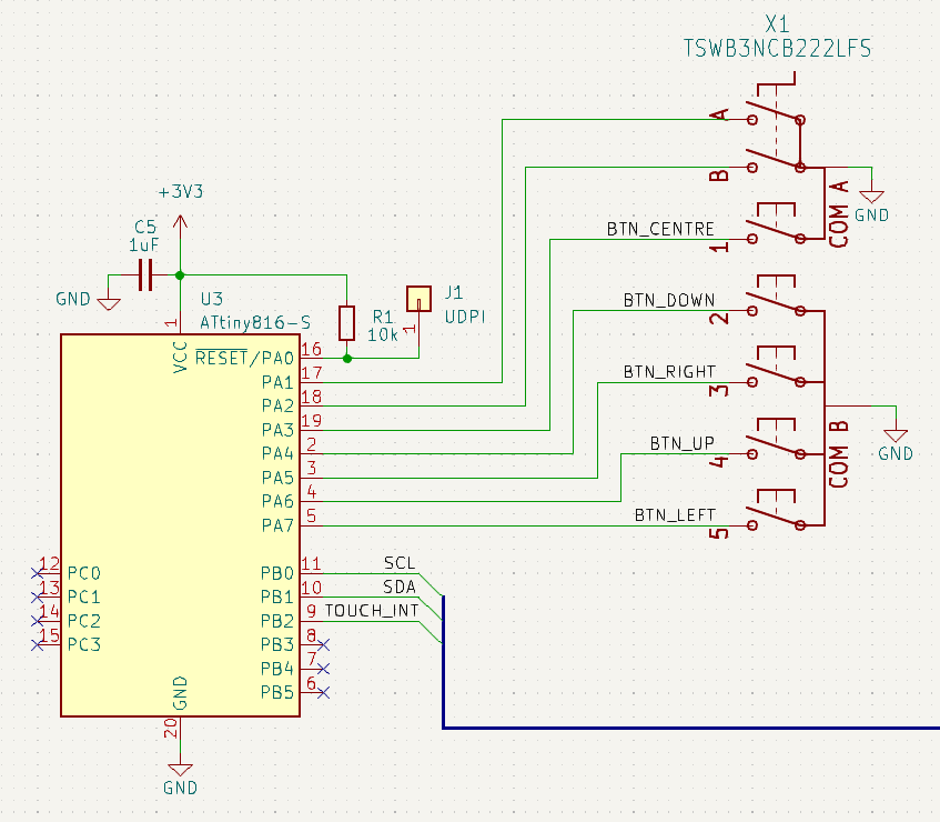
You can obviously get much more complicated than this. There's enough room between the faceplate and mainboard PCBs (especially in the top half of the PCB) to add even something like a micro-usb port, if your choice of microcontroller supports it.
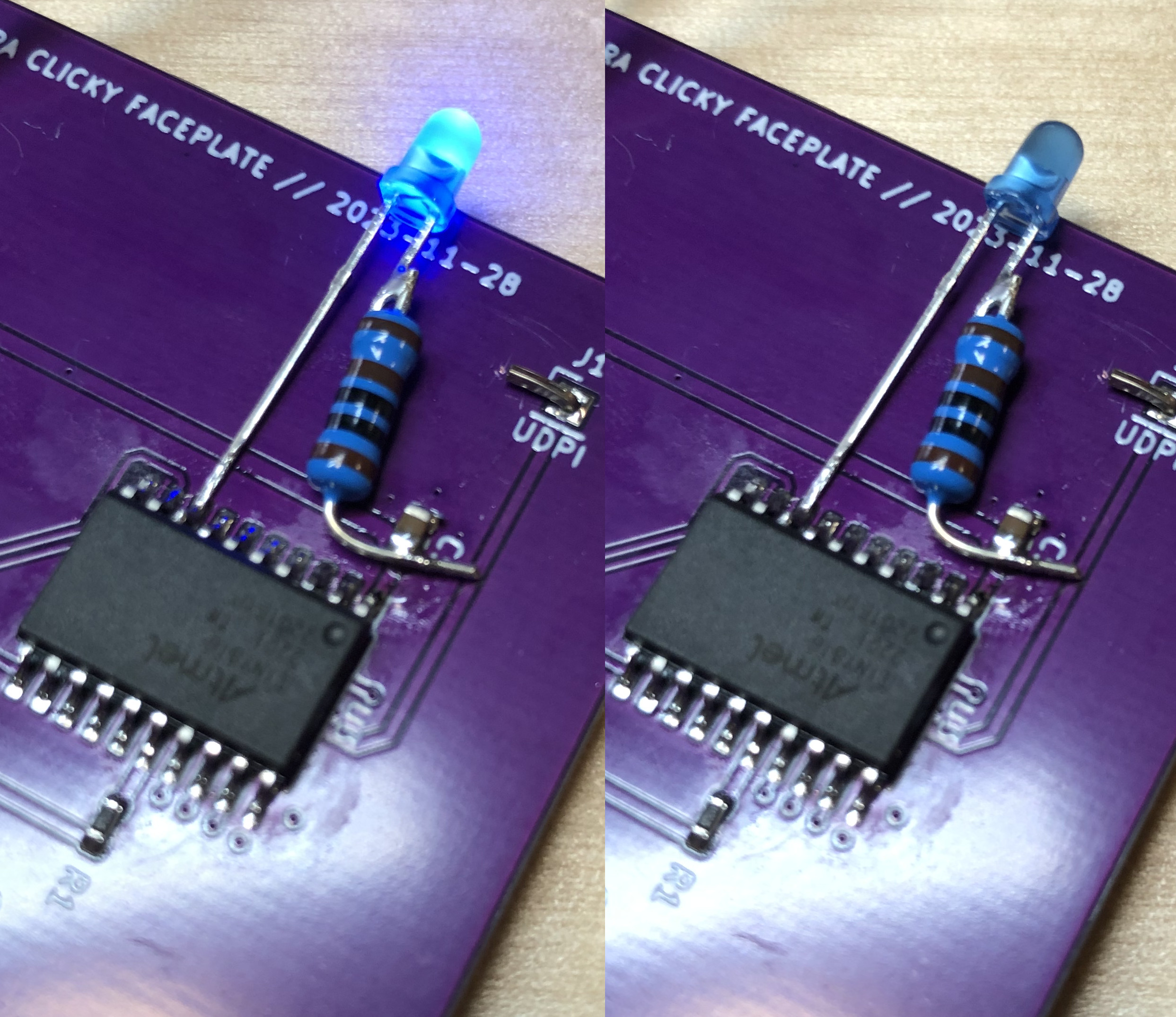
It may also be a good idea to add a small LED (plus a series resistor) to one of the unused GPIO pins to help with debugging; I left this out of the schematic and PCB because I'm confident in just soldering a through-hole LED directly to one of the legs of the ATTINY; YMMV!
Routing
Similar to the schematic design, we can start with most of the work done for us by copying the standard Tangara faceplate PCB and then deleting the components, fills, vias, and traces that we don't need (KiCad can even do most of this for us automatically).
In this case, this leaves us with just five components to place. Routing traces for each of these components is not too challenging, even for beginners, as it's all just slow-speed I²C signals and some GPIO lines.
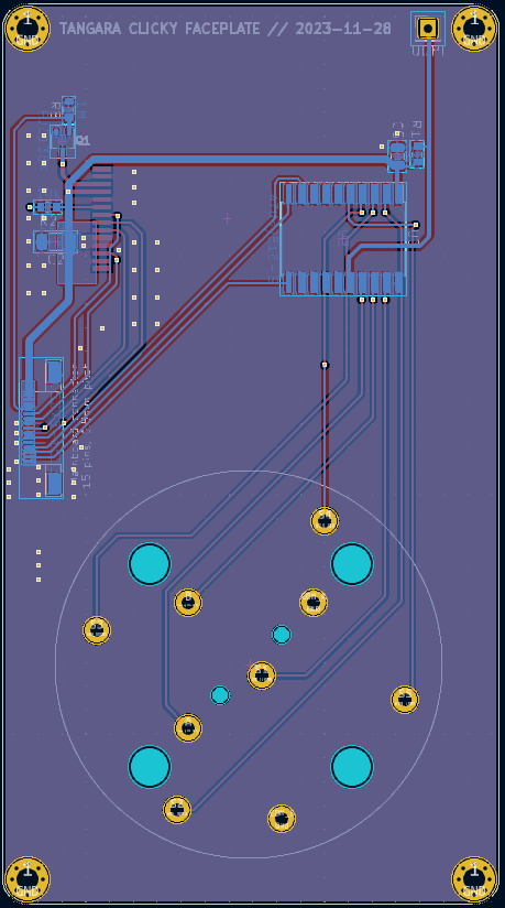
Ordering this PCB is also very cheap; I got five copies from JLCPCB for AUD$6.
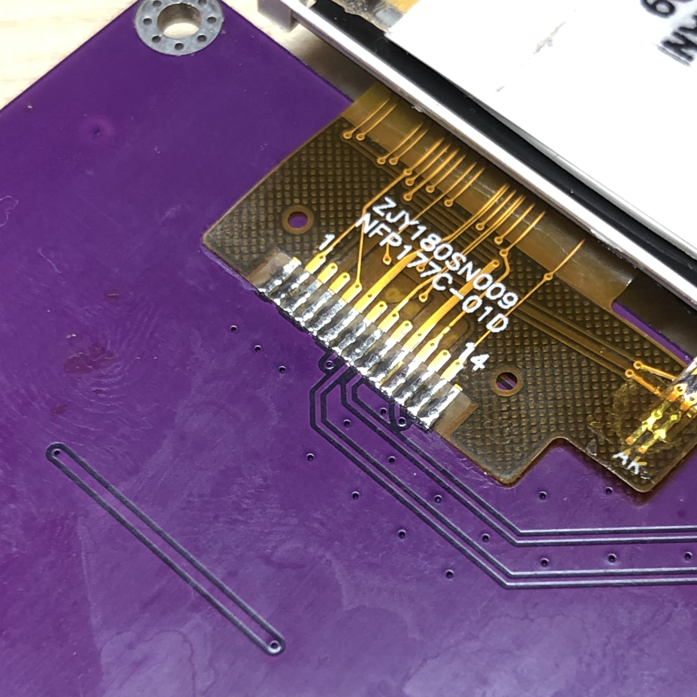
Soldering
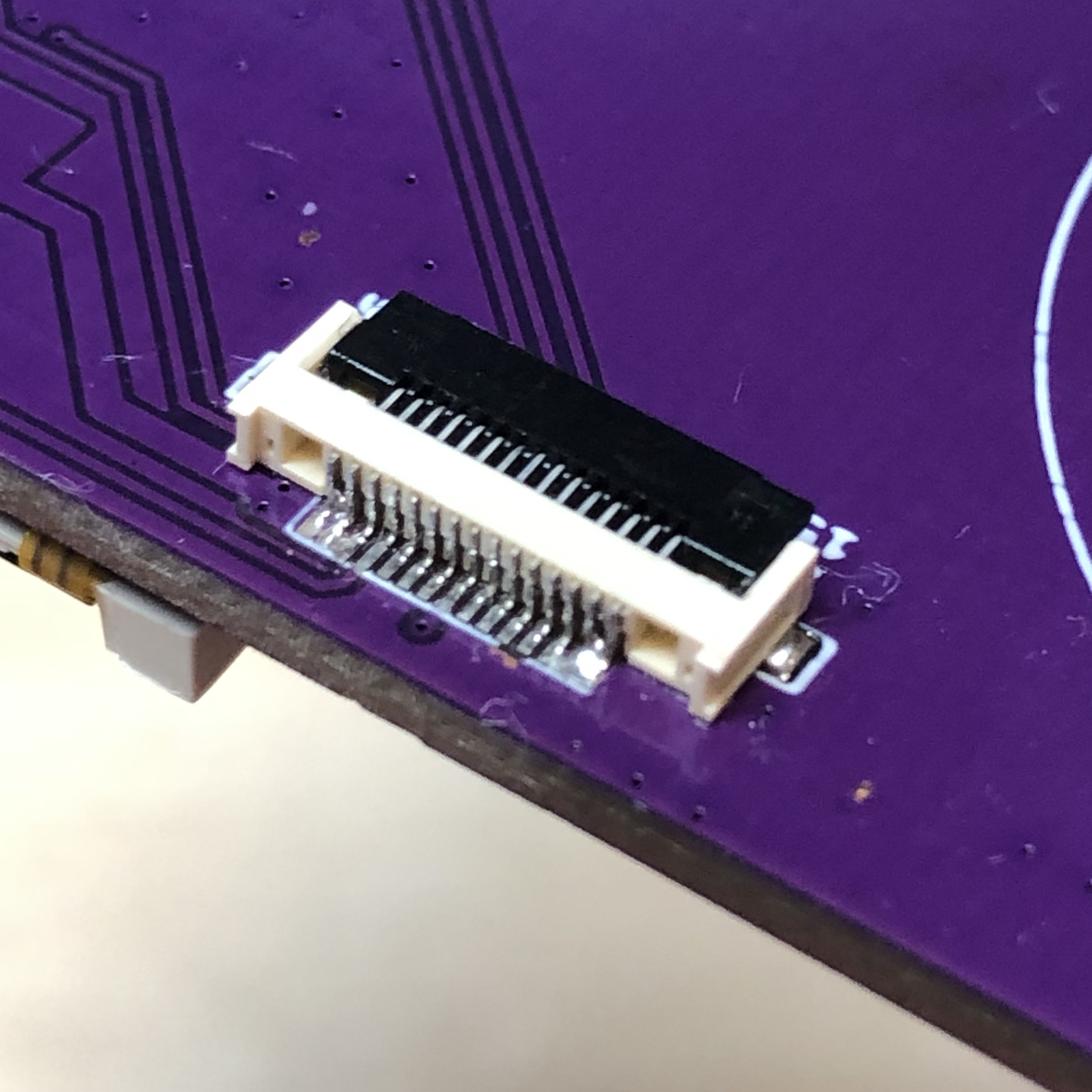
Soldering the board is something that comes down very much to your own preferences, skill level, and available tools. For the small MOSFET, passives, and the FFC connector, I usually lay down a small amount of solder paste by hand, place each component, then reflow the board on a hotplate. For the FFC connector especially I've found this to be the most consistent approach for hand assembly.
For assembling this faceplate in particular, I constrained myself to just my soldering iron and ordinary solder. The result looks like a complete mess, but it does work!
The display may seem intimidating, but there's a trick to soldering it easily: first ensure your iron is well cleaned and tinned. Then, lay down some flux over the pads. Next, line up the display's connector and solder one pad. Double check the alignment, then solder the pad on the opposite end. Lastly, go back across every pad until everything looks properly soldered.
Programming
The ATTINY816 I used has Arduino support, which makes putting together a working firmware very, very quick. First, I used a simple firmware that blinks an LED off and on in order to verify that my flashing setup worked.
Then I altered the firmware to blink the LED differently depending on how the rotary encoder is used.
After this, I added I²C support. Most I²C devices use a model where you first write a byte indicating which "register" you'd like to read, then begin a read to get the value of that register. Implementing this model with Arduino is quite straightforward:
static volatile uint8_t sRegister = 0;
void i2cReceive(int numBytes) {
  while (Wire.available()) {
    sRegister = Wire.read();
  }
}
void i2cRequest() {
  if (sRegister == 1) {
    // Encoder register. Returns the number of ticks since the last read.
    Wire.write(static_cast<uint8_t>(encoder.getPosition() + 127));
    encoder.setPosition(0);
  } else if (sRegister == 2) {
    // Button register. Returns the state of each button.
    // FIXME: Ideally we would set one bit per button. For this example, we
    // only make use of the centre button.
    Wire.write(digitalRead(kButtonCentre));
  }
}

void setup() {
  // [...]

  Wire.pins(kI2cSda, kI2cScl);
  Wire.onReceive(i2cReceive);
  Wire.onRequest(i2cRequest);
  Wire.begin(0x1C);
}
(The above code snippet is actually almost the entire file.)
ESP32 Changes
Finally, we need to modify Tangara's input driver to support using this clickwheel instead of the usual touchwheel. This largely involves deleting code.
Result
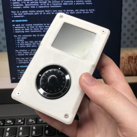
I asked Robin to throw together a modified case design for me and she came up with something that feels like it should be much more beige:
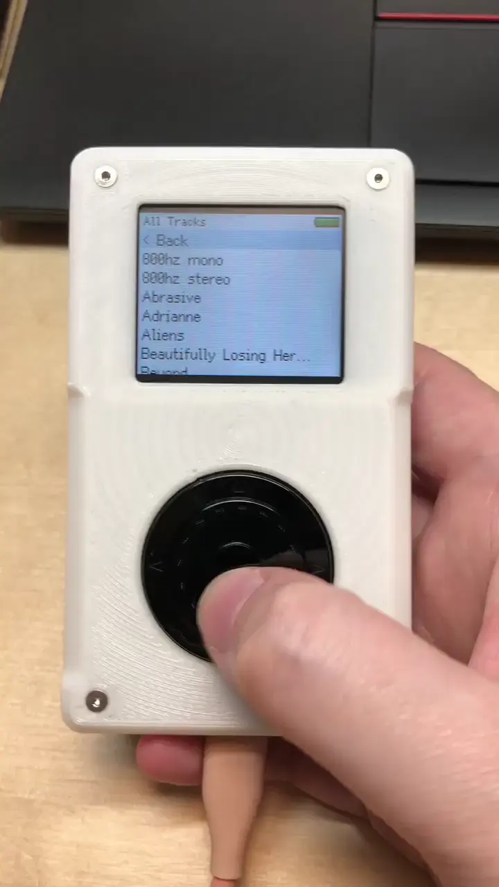
As you can see, it works pretty well! But looks kind of weirdly undersized!
I hope you can see that from this simple approach of using a low-power microcontroller to monitor an encoder, many different faceplates are possible. You could use the same approach to implement different kinds of touch interface, physical keypads, or even a physical d-pad and buttons to give the device more of a handheld console aesthetic.
Long-term, we'd love to produce more faceplate designs (in particular, I really want to make one that's just the FFC connector + display, a microcontroller, and then a protoboard-like array of through-hole pads).